English ▾

Scharge charger range and specifications

Scharge chargers from 7 kW AC to 400 kW DC: SC14, SC80, SC160 and the extended line, a selection guide, the consolidated specification table, 40 kW modular design and built-in protections.

03 · Product range

Product range and charger selection guide

The core line SC14 · SC80 · SC160 covers most needs, from car parks and buildings to fast-charging stations. The extended line — AC floor-standing, DC 40 kW and DC 200 – 400 kW — is supplied per project when the site, power supply or charging load has specific requirements.

Core
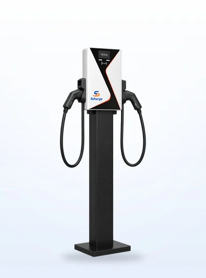
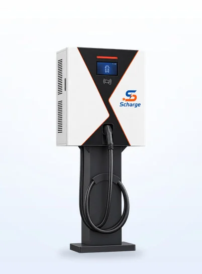
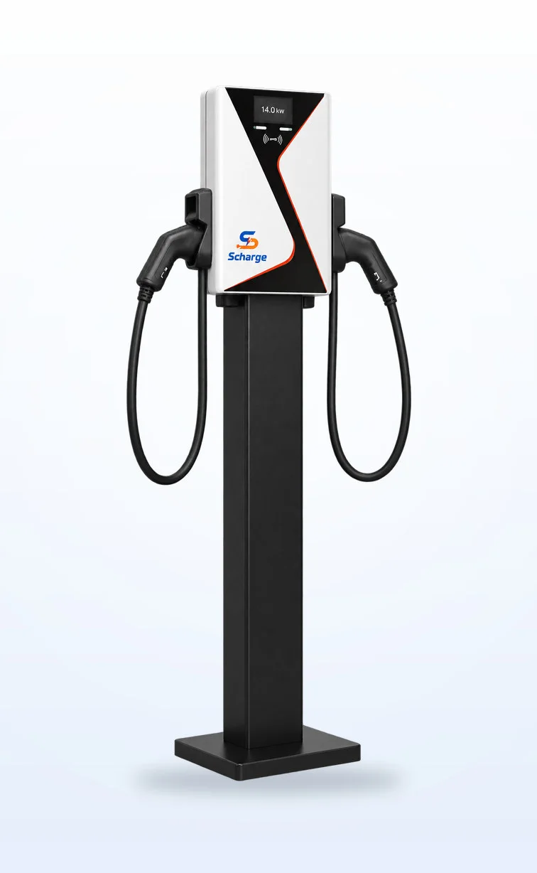
Scharge SC14 — AC · pedestal
SC14AC · pedestal2 × 7 kWType 2 · 1-phase
Extended
Scharge AC floor-standing — AC · metal enclosure
AC floor-standingAC · metal enclosure7 / 14 kW1 – 2 connectors
Extended
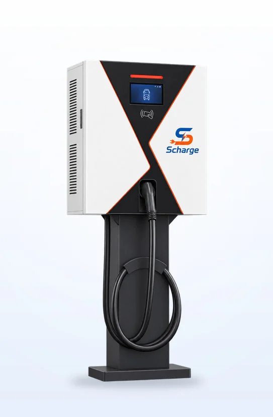
Scharge DC 40 kW — DC · wall-mounted
DC 40 kWDC · wall-mounted40 kW · 1 connector200 – 1 000 V
Core
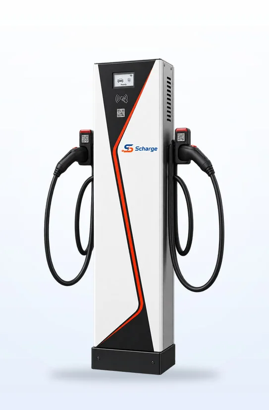
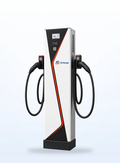
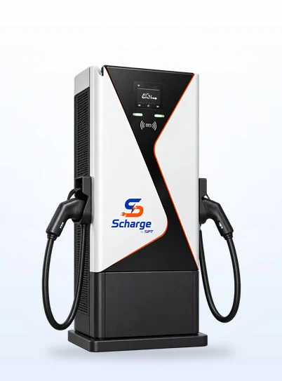
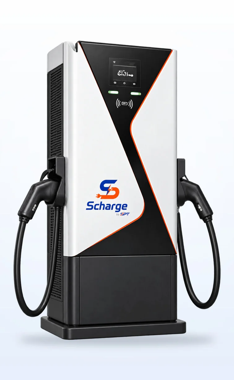
Scharge SC80 · SC160 — DC · floor-standing cabinet
SC80 · SC160DC · floor-standing cabinet80 / 160 kW2 connectors · 250 A
Extended
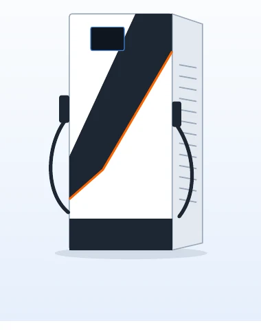
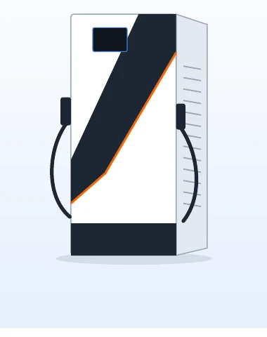
Scharge High-power DC — DC · large floor-standing cabinet
High-power DCDC · large floor-standing cabinet200 – 400 kW2 connectors · 300 A

Illustrations of the Scharge identity design; the DC 200 – 400 kW cabinet image is an illustrative sketch.

Choosing a charger by use case

Use caseTypical dwell timeRecommendationRationale
Apartment buildings, homes, overnight parking6 – 10 hoursAC 7 kW · SC14Slow charging to full, 1-phase supply, low infrastructure cost
Offices, schools, factories4 – 8 hoursSC14 · AC floor-standingTwo connectors per charger, serving several vehicles from one connection point
Shopping malls, hotels, public car parks1 – 3 hoursSC14 · DC 40 kWTop-up charging during shopping or stays
Service fleets, taxis, delivery20 – 60 minutes between shiftsSC80 · SC160Fast charging between shifts; SC160 serves two vehicles at once
Gas stations, rest stops, national highways15 – 40 minutesSC160 · DC 200 – 400 kWHigh power for 800 V platform vehicles, fast turnaround
Bus depots, electric trucks, fleet yardsShift-based depot chargingDC 200 – 400 kWHigh total power, supports parallel two-connector charging

Theoretical time to add 30 kWh

AC 7 kW4 h 17 min
DC 40 kW45 min
DC 80 kW23 min
DC 160 kW11 min

30 kWh corresponds to about 175 – 215 km at a consumption of 14 – 17 kWh/100 km. Calculated at constant power; actual time depends on the vehicle's charging acceptance limit, battery level (SOC) and battery temperature. A vehicle only accepts 160 kW on a high-voltage platform (see section 08).

04 · AC chargers Core line

SC14 — dual-connector AC charger, 2 × 7 kW

1-phase AC charger for standard charging at car parks, apartment buildings and offices. Two Type 2 connectors charge two vehicles simultaneously at 7 kW each; the single-connector 7 kW version shares the same unit body. Pedestal-mounted or wall-mounted.

Scharge SC14 AC charger with two Type 2 connectors on a pedestal, white and black enclosure with orange accents.
Scharge design illustration · Pro version with display
2 × 7 kWTwo connectors charge two vehicles simultaneously
Type 2AC connector, 5 m cable
≤ 3 WStandby power
OTA ≤ 5 minSoftware updates without interruption
Typical applications
  • Apartment buildings, homes, overnight parking
  • Offices, schools, factories
  • Hotels, shopping malls
  • Supplementary AC at fast-charging stations

Unit 260 × 103 × 420 mm · pedestal 255 × 205 × 1 175 mm

Electrical
Input / output voltageAC 220 V ±15% · 50 Hz ±1 Hz
Rated current32 A (1 connector) · 64 A (SC14)
Power per connector7 kW
Standby power≤ 2.8 W · ≤ 3 W (SC14)
Energy meteringAccuracy class 2
Communication and operation
Connectivity · start4G · QR scan, card tap
DisplayPro version has a display
BillingTime + service fee, or free of charge
Software updatesOTA via the platform, ≤ 5 min
GuidanceVoice announcements
Mechanical and installation
Unit (W×D×H)260 × 103 × 420 mm
Pedestal (W×D×H)255 × 205 × 1 175 mm
Enclosure · mountingPC + ABS · pedestal or wall-mounted
Cable · connector5 m · Type 2 (Type 1 to order)
Environment
Protection ratingIP54, indoor and outdoor
Operating temperature−25 ~ 50 °C
Vehicle typesBattery electric (BEV), plug-in hybrid (PHEV)
Built-in protection
  • Overvoltage
  • Undervoltage
  • Earth leakage
  • Surge
  • Over/under-temperature
  • Overcurrent
  • Overcharge
  • Full-charge cutoff

Specifications per the manufacturer's technical documentation; the standard version has no display. The official configuration (display, connector, cable length, mounting type) is as per contract.

05 · DC chargers Core line

SC80 · SC160 — floor-standing DC fast chargers

40 kW modular DC charging cabinet, two CCS2 connectors, output voltage 200 – 1 000 V for both 400 V and 800 V platform vehicles. Flexible power allocation: one connector takes the full cabinet power, or two connectors share it evenly when charging two vehicles simultaneously.

Scharge SC80 · SC160 DC fast-charging cabinet with two CCS2 connectors, touchscreen, white and black enclosure with orange accents.
Scharge design illustration
80 / 160 kWCabinet power, 40 kW modules
250 ARated current per CCS2 connector
200 – 1 000 VOutput voltage, 400 V and 800 V vehicles
10 inchTouchscreen, voice guidance
Typical applications
  • Public fast-charging stations
  • Taxi, delivery and service fleets
  • Gas stations, rest stops
  • Transport company depots

SC80: 750 × 520 × 1 700 mm · SC160: 750 × 650 × 1 700 mm

CCS1, GB/T and CHAdeMO connectors to order.

ElectricalSC80SC160
Cabinet power80 kW160 kW (120 kW configuration available)
Power architecture2 modules × 40 kW4 modules × 40 kW
Input voltageAC 380 V ±15% · 50 Hz ±1 Hz, 3-phase
Output voltage200 – 1 000 V DC
Rated current per connector250 A
Output modesOne connector at full power · two connectors sharing evenly
Output current tolerance≥ 30 A: ≤ ±1% · < 30 A: ≤ ±0.3 A
Energy meteringAccuracy class 1
Mechanical and environmentSC80SC160
Dimensions (W × D × H)750 × 520 × 1 700 mm750 × 650 × 1 700 mm
Enclosure · mountingSheet metal · floor-standing cabinet
Charging cable · connector5 m · CCS2 (Vietnam configuration)
Protection rating · temperatureIP54 · −25 ~ 50 °C
Installation altitude≤ 2 000 m (higher to special order)
Communication and operationSC80SC160
ConnectivityEthernet · 4G · 3G
Charging startQR scan · card tap · VIN recognition
Software updatesOTA via the platform
Built-in protection
  • Overvoltage
  • Undervoltage
  • Earth leakage
  • Surge
  • Over/under-temperature
  • Overcurrent
  • Overcharge

Specifications per the manufacturer's technical documentation. The official configuration (power, connector, cable length, accessories) is as per contract.

06 · Extended lines

Project-based extended lines

Complementing the core line where the site, power supply or charging load has specific requirements: a compact wall-mounted DC charger, a cabinet-type AC charger and a high-power DC cabinet for large stations. Supplied to order for each project.

Scharge DC 40 kW
Extended

DC 40 kW

Wall-mounted or on a base · 1 connector

Compact DC charger for garages, building car parks and service points with limited 3-phase supply. Has an emergency stop button and VIN recognition mode.

Power
40 kW
Output voltage
200 – 1 000 V DC
Input voltage
AC 380 V ±15% · 50 Hz
Power factor
≥ 0.99
Efficiency
module peak 95.5% · system 94%
Accuracy
voltage regulation ≤ 0.5% · current regulation ≤ 1%
Metering · protection
class 1 · IP54 · humidity ≤ 95%
Charging start
QR · card · VIN
Dimensions
unit 720 × 361 × 1 546 mm
Base
450 × 350 × 756 mm
Scharge AC floor-standing
Extended

AC floor-standing

7 kW · 14 kW · metal enclosure

Floor-standing cabinet version of the AC charger with a sheet metal enclosure, for indoor and outdoor use; electrical specifications equivalent to SC14, same platform connectivity.

Power
7 kW (1 connector) · 14 kW (2 connectors)
Rated current
32 A · 64 A
Voltage
AC 220 V ±15% · 50 Hz
Dimensions
350 × 250 × 1 400 mm
Connectivity
4G · OTA
Charging start
QR · card
Metering
class 2
Standby power
≤ 2.8 W · ≤ 3 W
Enclosure protection
IP54 · −25 ~ 50 °C
Charging cable
5 m, customizable
Scharge DC 200 – 400 kW
Extended

DC 200 – 400 kW

High-power cabinet · 2 connectors

For large fast-charging stations, bus depots and electric trucks. In addition to single-connector and even-sharing modes, supports parallel two-connector charging to increase charging power.

Configurations
200 · 240 · 320 · 400 kW
Architecture
40 kW modules
Current per connector
300 A
Output voltage
200 – 1 000 V DC
Input voltage
AC 380 V ±15% · 50 Hz
Dimensions
750 × 800 × 1 760 mm
Interface
10.1 inch touchscreen
Connectivity
Ethernet · 4G · 3G
Charging start
QR · card · VIN
Enclosure protection
IP54 · ≤ 2 000 m

Specifications per the manufacturer's technical documentation; dimensions as published by the manufacturer. The DC 200 – 400 kW cabinet image is an illustrative sketch.

07 · Specification summary

Specification summary for the product range

Quick comparison of the main specifications across the Scharge charger range, for equipment selection and design documentation.

Swipe horizontally to see the full table →

ParameterSC14CoreAC floor-standingExtendedDC 40 kWExtendedSC80CoreSC160CoreDC 200 – 400 kWExtended
Electrical
Charger typeAC · pedestalAC · floor-standing cabinetDC · wall-mountedDC · floor-standing cabinetDC · floor-standing cabinetDC · floor-standing cabinet
Power2 × 7 kW7 / 14 kW40 kW80 kW160 kW¹200 – 400 kW
Connectors · type2 · Type 21 – 2 · Type 21 · CCS22 · CCS22 · CCS22 · CCS2
Input supply1-phase 220 V1-phase 220 V3-phase 380 V3-phase 380 V3-phase 380 V3-phase 380 V
Output voltageAC 220 VAC 220 V200 – 1 000 V200 – 1 000 V200 – 1 000 V200 – 1 000 V
Current per connector32 A32 A—250 A250 A300 A
Input power²14.1 kVA7.0 / 14.1 kVA43.0 kVA86.0 kVA171.9 kVA215 – 430 kVA
Energy meteringclass 2class 2class 1class 1class 1class 1
Mechanical and environment
Dimensions W × D × H (mm)260 × 103 × 420³350 × 250 × 1 400720 × 361 × 1 546750 × 520 × 1 700750 × 650 × 1 700750 × 800 × 1 760
Enclosure materialPC + ABSsheet metal—sheet metalsheet metalsheet metal
Protection ratingIP54IP54IP54IP54IP54IP54
Operating temperature−25 ~ 50 °C−25 ~ 50 °C—−25 ~ 50 °C−25 ~ 50 °C−25 ~ 50 °C
Installation altitude———≤ 2 000 m≤ 2 000 m≤ 2 000 m
Charging cable5 m5 m—5 m5 m5 m
Communication and operation
Connectivity4G4G—Ethernet · 4G · 3GEthernet · 4G · 3GEthernet · 4G · 3G
Interfacedisplay (Pro version)——10 inch touchscreen10 inch touchscreen10.1 inch touchscreen
Charging startQR · cardQR · cardQR · card · VINQR · card · VINQR · card · VINQR · card · VIN
OTA updatesyesyesyesyesyesyes

¹ The SC160 enclosure has a 120 kW configuration (3 modules). ² Reference: DC chargers calculated at 94% efficiency and power factor 0.99; AC chargers at rated current. ³ Unit body dimensions; pedestal 255 × 205 × 1 175 mm. — : not yet published in the current manufacturer documentation; to be confirmed per ordered configuration.

Options to order

Charging cable lengthType 1, GB/T, CCS1, CHAdeMO connectorsDisplay (AC Pro version)Pedestal or wall-mounted (AC)Base (DC 40 kW)120 kW configuration (SC160 enclosure)Installation above 2 000 m (DC floor-standing cabinets)

08 · Core technology

40 kW modular design and power allocation

Scharge DC chargers are built from 40 kW rectifier modules. The controller allocates modules to each connector according to vehicle demand, making full use of cabinet power whether charging one or two vehicles and allowing future power upgrades.

  1. 1
    One vehicle

    All modules are pooled to one connector — the vehicle receives the highest power within the connector's current limit (250 A for SC80 · SC160).

  2. 2
    Two vehicles

    Modules are split evenly between the two connectors — each vehicle receives half the cabinet power, and the two sessions run independently.

  3. 3
    One module platform

    DC cabinets from 80 kW to 400 kW share the same 40 kW module; maintenance and replacement module by module.

Example SC160: 4 modules × 40 kW, two CCS2 connectors.

Maximum single-connector power by vehicle battery voltage

400 V platform vehicles800 V platform vehicles0801602403202004006008001000SC80 · 80 kWSC160 · 160 kWDC 320 kW · 300 kWVehicle battery voltage (V)Max. power, 1 connector (kW)

For 400 V platform vehicles, the 250 A limit caps single-connector power at about 100 kW. SC160 delivers its full power when charging two vehicles simultaneously (2 × 80 kW) or an 800 V platform vehicle (160 kW).

Simplified model: P = min(rated power, U × maximum connector current I). Does not account for the vehicle's charging curve or module current limits. The shaded bands are typical battery voltages of 400 V and 800 V vehicles.

Vehicle battery voltageSC80SC160 · 1 vehicleSC160 · 2 vehicles simultaneouslyDC 320 kW · 1 vehicle
400 V platform vehicle80 kW100 kW2 × 80 kW120 kW
800 V platform vehicle80 kW160 kW2 × 80 kW240 kW

DC charging session sequence (principle)

  1. 1ConnectPlug in the CCS2 connector, mechanical connector lock, vehicle identification.
  2. 2CheckParameter exchange with the BMS; insulation check of the DC circuit before energizing.
  3. 3Pre-chargeBattery voltage is matched; DC contactors close once both sides are balanced.
  4. 4ChargeModules deliver current as requested by the BMS; temperature, current and voltage are monitored continuously.
  5. 5EndCurrent ramps down to 0, contactors open, the connector unlocks, session data is finalized.

General sequence for conductive DC charging; voltage and current parameters are requested by the vehicle's battery management system (BMS) and met by the charger within its ratings.

Source: Technical dossier of the Scharge EV charging station solution, SPT · SST Center, version 09/2026.

Bring a Scharge charging station to your site

Send us your requirements and CD Restop will survey the site and propose a suitable configuration.

Request a site survey0981 107 900